Distance & movement sensors
Various sensors that can used with microcontrollers to track persons, objects, colours or other distance.
- Motion Tracking with Sensors for Microcontrollers
- UltraSonic of PIR sensor Arduino & Touchdesigner or Isadora
- LiDAR with Arduino - TF-Luna Sensor
- Grove - IR Distance Interrupter v1.2
- Infrared (IR) break-beam sensor
- Time of Flight Distance Sensor VL53L4CD
- IR Distance Sensor SHARP GP2Y0A02YK with Arduino
Motion Tracking with Sensors for Microcontrollers
Research by Blackbox into various sensors that can used with microcontrollers to track persons, objects, colours or other motions. What kind of differents sensors are there to use and what are the pro’s and con’s of each sensor?
Sensors of Interest:
Sensing Distance and Proximity:
- Ultrasonic Sensor
- Infrared Sensors / IR
Infrared (IR) break-beam -
PIR Motion Sensor
-
Microwave Doppler Radar Sensor
-
Grove IR Disctance interrupter
More advanced sensing:
- LiDAR,
- ToF, Time-of-flight sensors
- HuskyLens AI Vision
Can also be used:
- LDR Photocell sensors
- Capacitance sensors
- PhotoDiodes
Ultrasonic Sensor
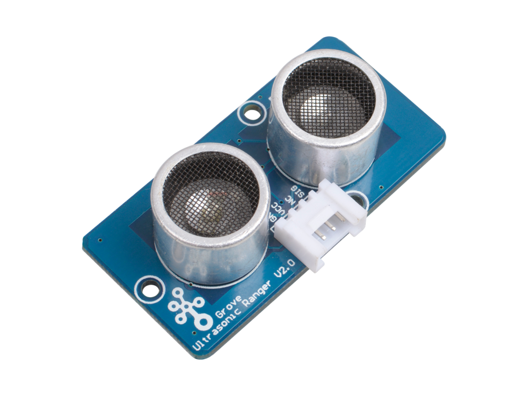
Example project
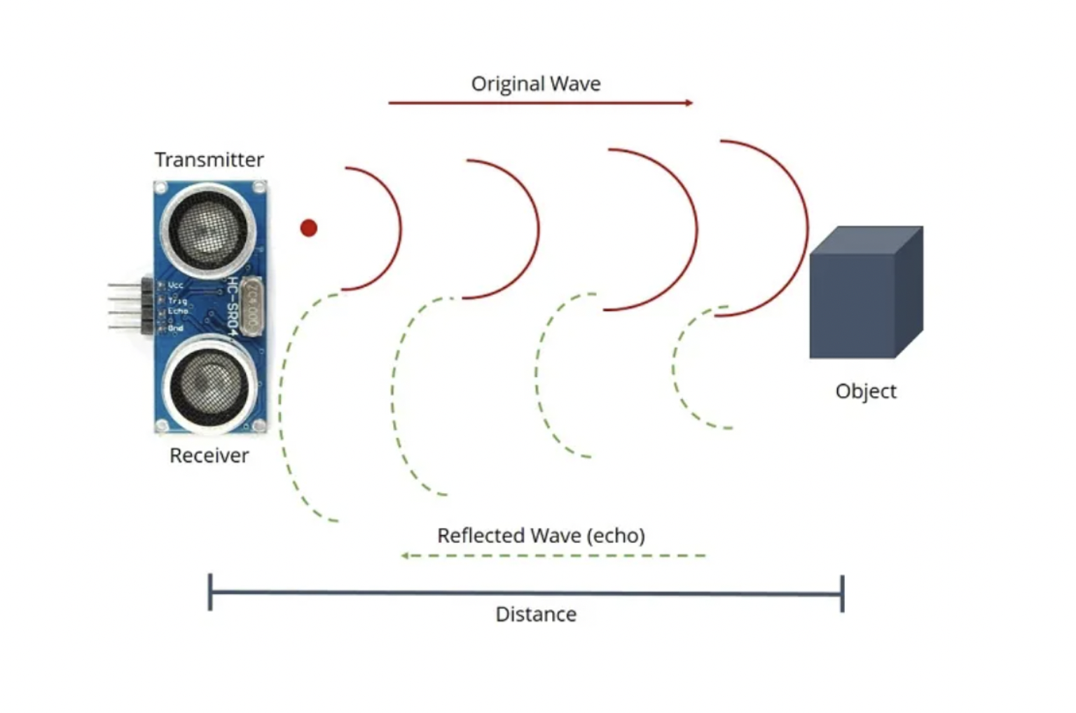
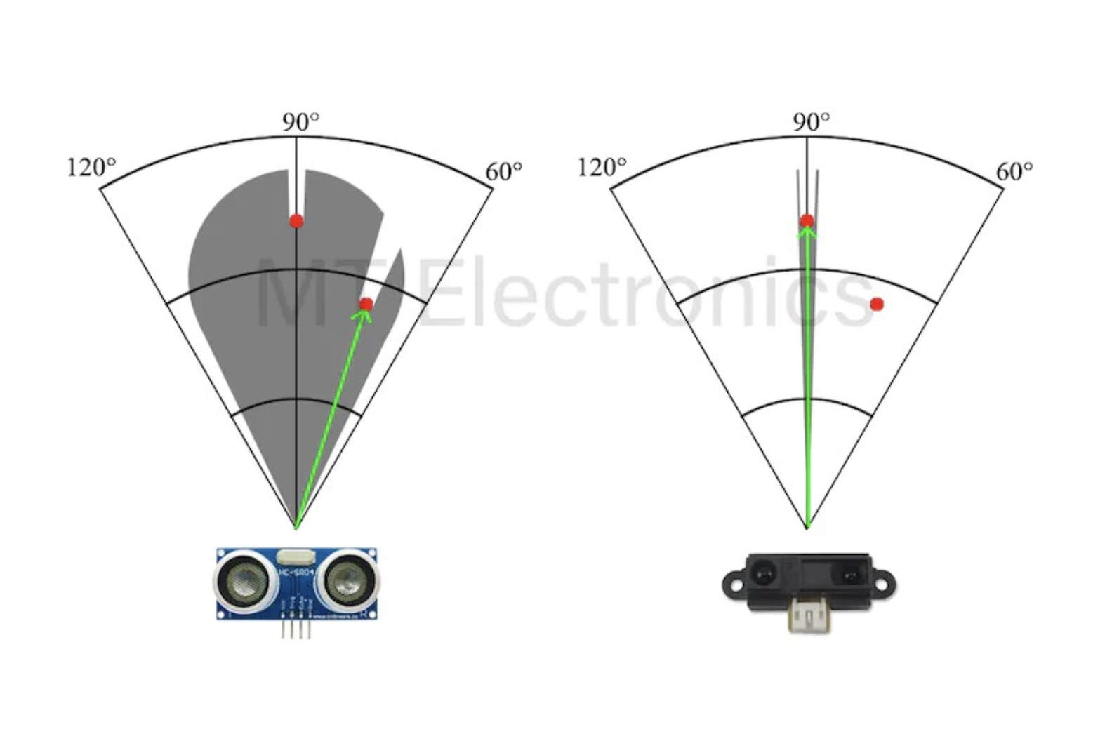
The Ultrasonic Sensor is arguably the most common distance measuring sensor, also known as the Sonar sensor. It detects the distance to objects by emitting high-frequency sound waves. The object needs to be in line with the sensors not so wide range. Used a lot in DIY distance measurement projects, robotics, smart cars, drones. Most common used sensor is the HC-SR04.
+
- not affected by colour object or transparency.
- Works well in dim places
-
- limited detection range
- Not good in tracking fast objects
- Unable to measure objects with extreme textures or surfaces.
Detection is good for example; knowing if someone ‘entered’ the space and switch on video. Not so good for when you want one or multiple persons tracked.
Infrared Sensor (IR)

Example project
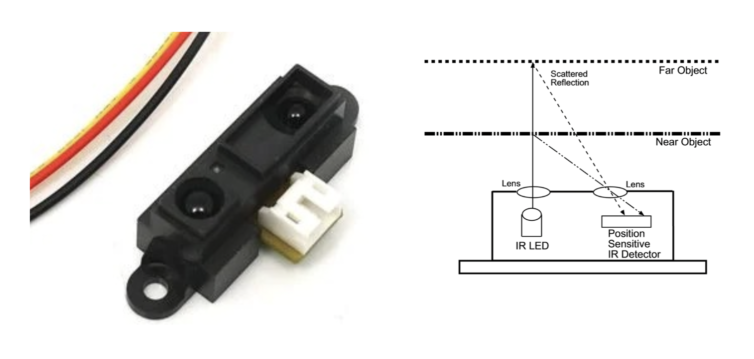
IR distance sensors work through the principle of triangulation; measuring distance based on the angle of the reflected beam. Used a lot in TV’s, computers and laptops, distance measurement projects, security systems, monitoring and control applications.
Recommended sensor: 80cm Infrared Proximity Sensor - GP2Y0A21YK
+
- Small size
- Daytime and Nighttime usage
- Able to measure the distance of objects that have complex surfaces unlike ultrasonic sensors
-
- Limited measurement range
- Affected by environment conditions and hard objects
PIR Motion Sensor
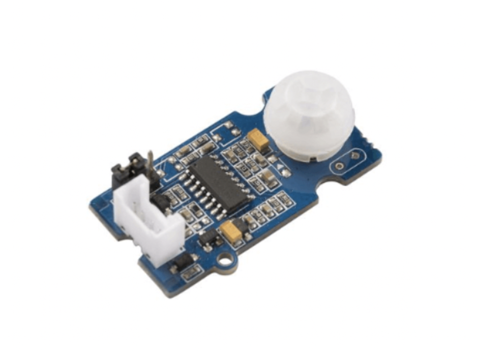
Example project
Passive infrared (PIR) sensors are sensitive to infrared (IR) rays and are mostly used for motion detection where humans move in or out of the sensor range.
Used a lot in appliances and gadgets for home or business (room detection). Also in DIY projects.
All living objects, whose body temperature is more than 0°C, emit the heat in form of infrared radiation through their body, also called as thermal radiations. This Radiated energy is invisible to human eye. These Signals can be detected by using PIR sensor which is specially designed for such purpose.
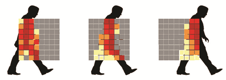
PIR sensor i.e. Passive Infrared Sensor, passive word indicates PIR Sensor does not generate or radiate any energy for detection purposes. PIR Sensors don't detect or measure "HEAT"; they detect the infrared radiation emitted or reflected from objects.They are small, inexpensive, low power and easy to use. They are commonly found at home, medical, factories etc. areas.
Link to more info about PIR sensors
Microwave Doppler Radar Sensor
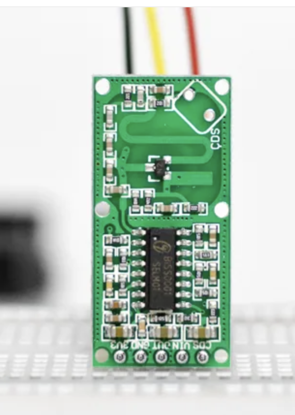
For most of our Arduino projects that require knowing if someone has left or entered the area, the PIR sensor is an excellent choice. However, because they only detect movement from living things, they will generate fewer false alarms.
This is where a microwave sensor like the RCWL-0516 comes in handy. The RCWL-0516 microwave sensor detects any movement from any object and does not rely on heat signatures, making it more reliable in hot environments where a PIR sensor may not be as effective.
More about Doppler Microwave sensors here
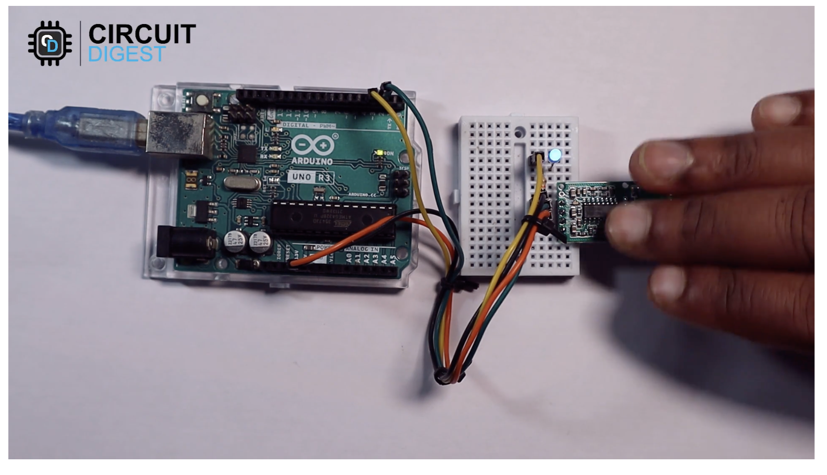 And a tutorial explaining the RCWL-0516 Microwave Doppler Radar sensor and running a beginner test can be found here by CircuitDigest .
Grove IR Disctance interrupter
is used to detect any object blocking the path of light. The module consists of an IR LED and a photosensor (phototransistor) pair. The light emitted by the IR LED gets reflected by any object placed in front of the sensor and this reflection is detected by the photosensor(phototransistor). Any white (or lighter) colored surface reflects more than black (or darker) colored surface.
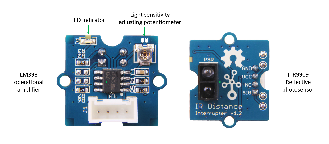
When the reflected light is detected, it produces Digital HIGH (or Binary 1) output on the SIG pin. The on-board LED indicator will also glow. If no reflection is detected or if the object is too far from the sensor, the output on the SIG pin stays at Digital LOW (Binary 0). The on-board LED indicator will be off as well. The detectable range of this sensor is 7.5–40 cm. The module incorporates a Rail-to-Rail Operational Amplifier to amplify the output of phototransistor. There is a potentiometer which can be used to adjust the gain of the amplifier, that is, sensitivity of detection.
More info & sample project here
Lidar TF Luna

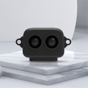
TF-Luna is a single-point ranging Lidar based on the TOF principle. With its unique optical and electrical design, it adopts an 850nm infrared light source to achieve stable, accurate, and highly sensitive distance measurements.
More information here
Lidar TF Luna Sensor example project
UltraSonic of PIR sensor Arduino & Touchdesigner or Isadora
Deze manual werkt voor PIR (passive infrared) bewegings sensor en ook voor de Ultrasonic sensor
Beschrijving PIR sensor (Duits)
https://www.reichelt.nl/nl/nl/raspberry-pi-infrarood-bewegingsmelder-hc-sr501-rpi-hc-sr501-p224216.html?PROVID=2809&gclid=CjwKCAjwzJmlBhBBEiwAEJyLu7b6GP911-3vaEA33hXK1vssSrwNGtU83omn4zjNUqw3wLPmZsHYzRoCQnEQAvD_BwE
Detectieafstand: 3-7m
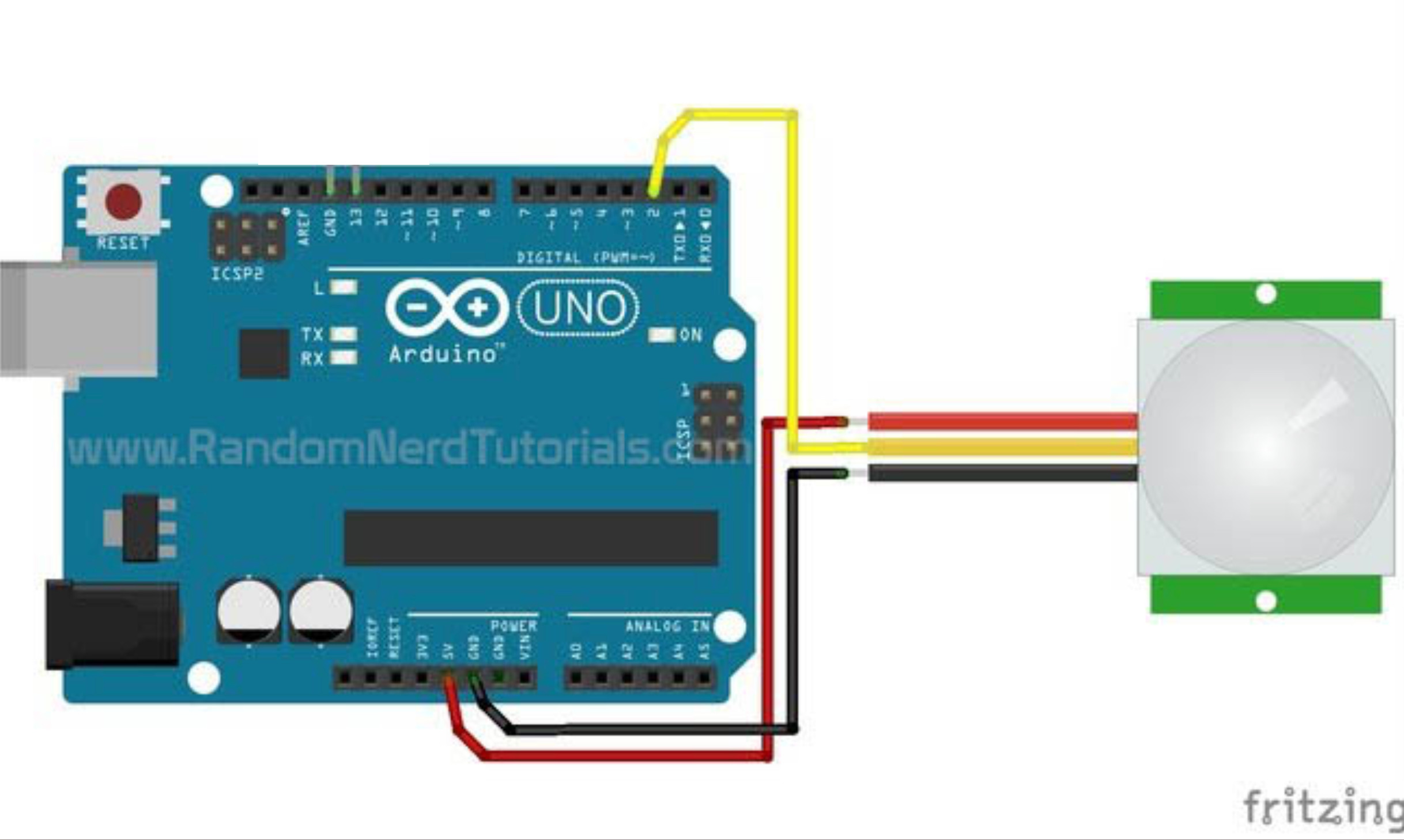
Code voor PIR sensor:
Test of het werkt:
maak in Arduino verbinding met de Arduino door de juiste board en poort te kiezen, Board: Arduino Uno & poort Mac: /dev/cu.usbmodem1301 Serial Port (USB), Poort PC: COM3
installeer de code op de Arduino door links bovenin op het pijltje te drukken.
test de code en setup door rechts boveninn op het vergrootglaasje te drukken.
werkt het niet neem contact op met Blackbox medewerker voor een check van je setup.
Data ontvangen in Isadora:
Zet serial monitor in Arduino uit
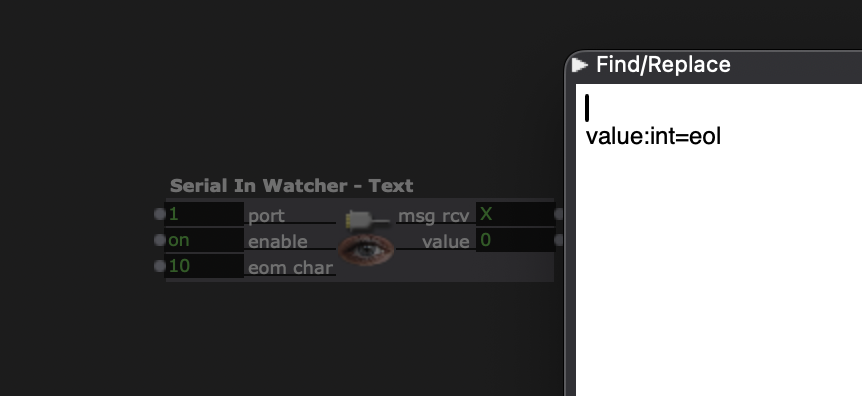
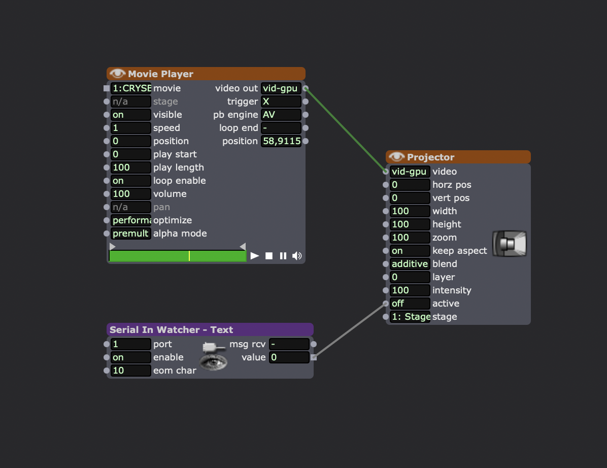
gebruik de actor: serial in watcher text
verander de instelling van de serial in watcher actor:
open de actor by double klikking it and fill in this code : value:int=eol
in actor put eom char on 10
Zet verbinding met Arduino aan:
1 menu > communications > serial port setup
2 Port 1 > Device > Select > kies USB poort
Als Isadora de poort niet laat zien of zegt dat hij Busy is kies dan None en daarna weer de USB poort. > OK
Menu > communications > Enable serial ports

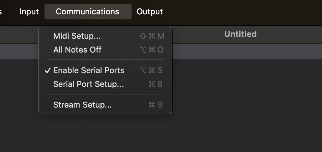
Aan de rechterkant van de serial in watcher actor zou de waarde in msg rcv moeten veranderen van - naar X
En value moet veranderen van 0 naar 1
Voorbeeld Isadora met een video:
--------------------------------
Beschrijving ultrasonic sensor:
https://randomnerdtutorials.com/complete-guide-for-ultrasonic-sensor-hc-sr04/
Detectieafstand: 2cm tot 400cm
Werkt goed op solid surface, stoffen zoals kleding is minder accuraat.
Installatie Ultrasonic sensor check volgende tutorial >>>
Data > touchdesigner:
https://www.youtube.com/watch?v=lkudxFrwPXU
Let op als je in Touchdesigner of Isadora de input wilt testen dan moet je in Arduino je Serial Monitor uitzetten.
Anders kan de software niet communiceren met de Arduino .
Deze tutorial is getest door Simone van Dordrecht (Blackbox medewerker IBB)
LiDAR with Arduino - TF-Luna Sensor
Als je iets anders wilt dan Ultrasonic Sensor HC-SR04 kwa afstand namelijk meer afstand met minder ruis kun je kiezen voor de TF-Luna Sensor. Dit is een Lidar sensor die met behulp van een laser de afstand tot een object meet tussen 0,2 en 8 meter.
> De TF Luna LiDAR-afstandsmeter biedt een bereik van 0,2 m-8 m, een resolutie van 1 cm en een nauwkeurigheid van ±6 cm @ (0,2 m-3 m) <
Materiaal:
Arduino Nano + USB kabel
TF-Luna Sensor
Breadboard
Jumper wires male/male
kabel verbinders voor snel testen zonder solderen
Ik heb om dit aan de praat te krijgen de volgende bron gebruikt:
https://www.diyengineers.com/2022/06/02/lidar-how-to-use-with-arduino/
Op deze site kun je belangrijke documenten downloaden zoals datasheet en user manual maar die heb ik amper nodig gehad.
https://en.benewake.com/TFLuna/index.html
Shop:
https://eu.robotshop.com/nl/products/benewake-tf-luna-8m-lidar-afstandssensor
Wat ik lastig vond bij deze is dat er geen JST GH1.25 - 4P naar Dupont verloopjes bij zaten dus heb ik de kabel gestript en waco verbindingsklemmen gebruikt om te testen. Solderen kan natuurlijk ook maar ook dat was me even teveel werk.
Kiwi Electronics verkoopt ze met de handige kabels maar niet op voorraad. https://www.kiwi-electronics.com/nl/tf-mini-s-lidar-module-10359?search=lidar
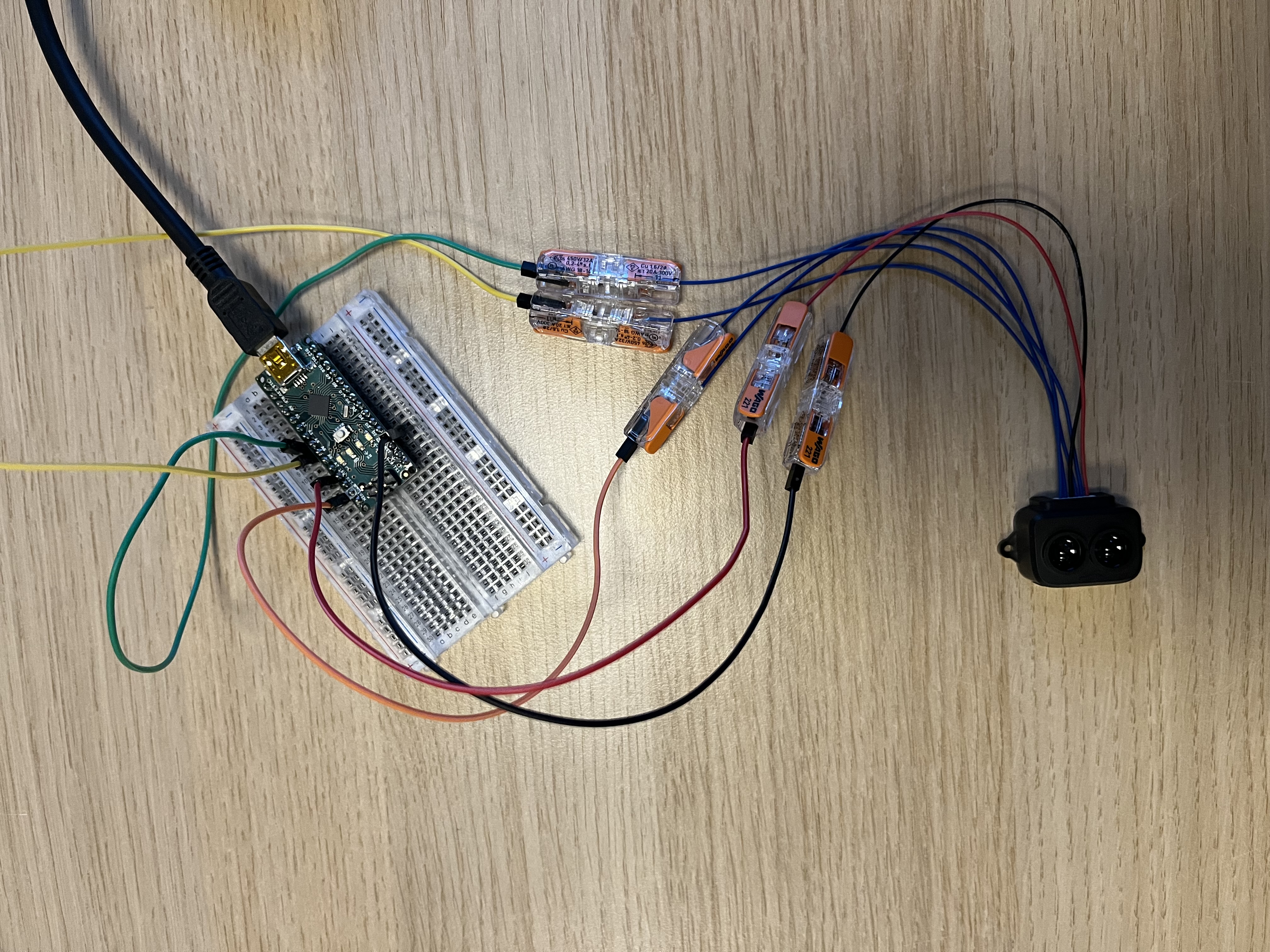
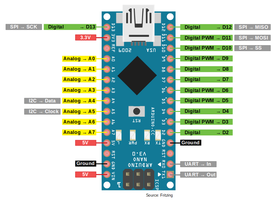
Ik heb een Arduino Nano gebruikt. In de tutorial wordt de Arduino Uno gebruikt en voor data overdracht de poorten ICSP2. Volgens bovenstaand schema kan je daarvoor IC2 pins Analog A4 & A5 gebruiken.
De 6e kabel hoef je niet te gebruiken.
Installeer Arduino software
https://www.arduino.cc/en/software
Arduino Library:
https://github.com/budryerson/TFLuna-I2C
Verbind de arduino met mini usb kabel aan je computer, kies links bovenin de Arduino software venster je type arduino board en de usb poort
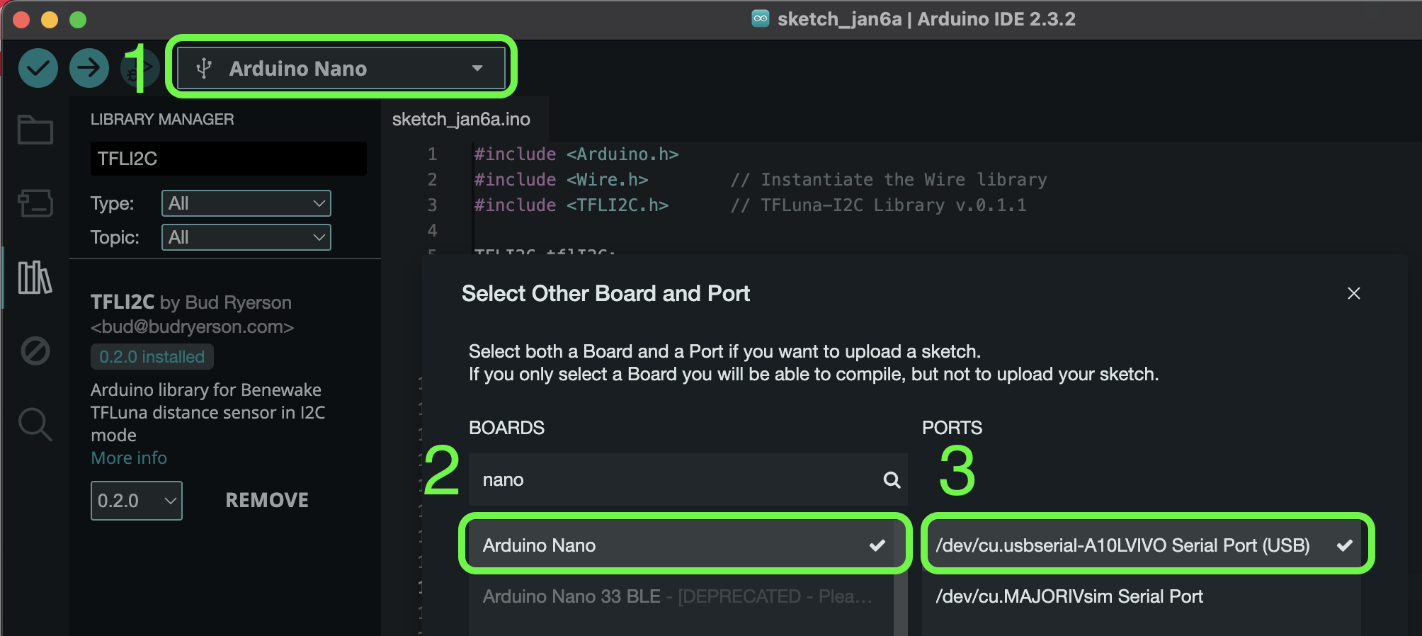
Volg de aanwijzingen in de tutorial via link bovenaan dit document om de library via Arduino software te installeren.
Ga bovenin je menu balk in de arduino software naar Tools > Serial Monitor.
Zet rechts onderin 9600 Baud om naar 115200 Baud, anders krijg je rare resultaten.
Houd je hand boven de lidar sensor en zie de waardes veranderen.
Als je nog info mist in deze uitleg of iets is niet duidelijk laat het me dan weten dan pas ik het aan.
Simone.vandordrecht@hku.nl
Voorbeeld project: intensiteit licht LED pixel ring beïnvloeden door afstandmeting Lidar TF Luna sensor
Materiaal:
Neo pixel ring 12 of 16 pixels
Arduino Nano + USB kabel
TF-Luna Sensor
Breadboard
Jumper wires male/male
Resistor 330 Ω tot 470 Ω
Universal AC adapter 5V
Terminal block to 2.1mm DC barrel jack - Female
Bronnen voor testen:
https://www.diyengineers.com/2022/06/02/lidar-how-to-use-with-arduino/
https://learn.adafruit.com/adafruit-neopixel-uberguide/arduino-library-installation
https://medium.com/@elonskolnik/arduino-uno-tutorial-neopixel-ring-setup-9fafc099c89a
https://chatgpt.com/share/6787fc7b-e388-8006-98cc-3678b193ec44
Combineren:
Soldeer de kabeltjes van de TF Luna aan jumper wires en gebruik krimpkousjes voor bescherming
Power de Pixelring apart van de Arduino, zorg dat de ground wel doorlust naar de ground van arduino en TF Luna.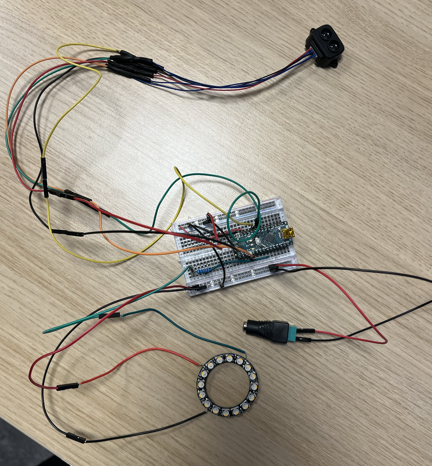
(Duidelijk schema hiervan moet ik nog maken)
Alternatief voor draadloos project: Gebruik een powerbank 5V voor stroom voor de arduino en een batterij pack bijvoorbeeld 4x AA voor de stroom voor pixelring. Foto hiervan volgt..
Meer info kun je hier vinden:
https://bookstack.hku.nl/books/arduino-things/page/controlling-ledstrips-with-arduino
Code:
Grove - IR Distance Interrupter v1.2
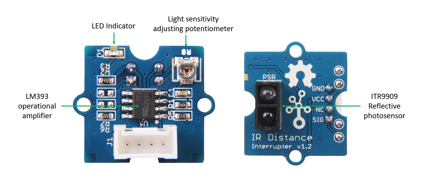
Grove - IR Distance Interrupter is used to detect any object blocking the path of light.
The light emitted by the IR LED gets reflected by any object placed in front of the sensor and this reflection is detected by the photosensor(phototransistor). Any white (or lighter) colored surface reflects more than black (or darker) colored surface.
You can borrow this sensor for testing from Blackbox workshop employe at location IBB: blackbox.ibb-pastoe@hku.nl
When the reflected light is detected, it produces Digital HIGH (or Binary 1) output on the SIG pin. The on-board LED indicator will also glow. If no reflection is detected or if the object is too far from the sensor, the output on the SIG pin stays at Digital LOW (Binary 0). The on-board LED indicator will be off as well.
The detectable range of this sensor is 7.5–40 cm.
There is a potentiometer which can be used to adjust the gain of the amplifier, that is, sensitivity of detection. Use the best fitting scredriver for this and be very sensitive!!!
Note
This product is mildly sensitive to non-IR radiations also and hence any bright light on photosensor impairs or disturbs IR light detection.
Material required
- Grove - IR Distance Interrupter v1.2 × 1
- Arduino UNO (other models also are fine) × 1 + power cable (sold seperately)
- Grove cable × 1 (some sensors come wit cable, different lengths available)
- Grove - Base Shield × 1
Connections
1.Connect Base shield to arduino board Grove, connect IR Distance Interrupter v1.2 to Arduino UNO with Grove cable. port D6
2.Place and hold the Reflective photosensor towards white(or light) colored surface. For adjusting sensitivity read this
3.Create an Arduino sketch and copy the below code into it.
void setup() {
Serial.begin(9600);
pinMode(6,INPUT);
}
void loop() {
while(1) {
delay(500);
if(digitalRead(6)==LOW) {
Serial.println("Somebody is here.");
}
else {
Serial.println("Nobody.");
}
}
}
5.Connect Arduino to your comuter & Upload the code.
If you do not know how to upload a Arduino sketch, please visit https://www.arduino.cc/en/Guide/Windows for Windows user or https://www.arduino.cc/en/Guide/MacOSX for Mac user.
6.When the path of light is blocked by some object, you would see "Somebody is here." in Serial Terminal else you will see "Nobody."
For connecting with Isadora read this
Source:
https://wiki.seeedstudio.com/Grove-IR_Distance_Interrupter_v1.2/
Infrared (IR) break-beam sensor
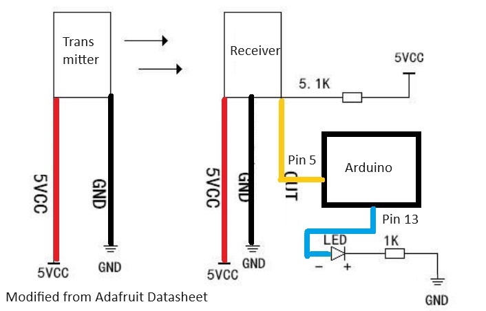
Infrared (IR) break-beam sensors are an easy way to detect movement. This sensor has a transmitter and receiver part. Point the transmitter at the receiver to create a light beam that will trigger the receiver if this bundle is interrupted.
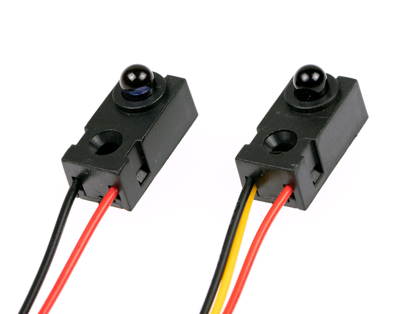
For this test i didn't use an LED as mentioned in the code and tutorial (see sources bottem of the page)
You can leave it out of the setup if you don't need it and connect the data(yellow wire) directly to pin 5 (digital) on the arduino.
Because it works with infrared light, use it indoors and close the curtains and maybe don't use halogen lights ;) I made that mistake.
Material
- Arduino UNO (other models also are fine) × 1 + power cable (sold seperately)
- - Sensor: https://www.kiwi-electronics.com/nl/infrarood-straal-detector-5mm-leds-1577?search=kw-1516
Assembly
1. If you buy this sensor new you will likely receive this without jumper wires. To make testing easy solder on some jumper wires.
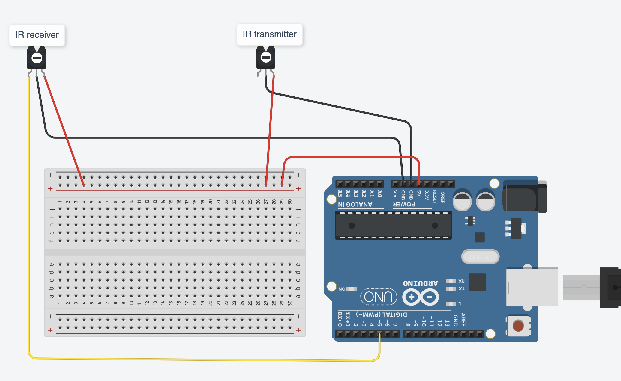
2. Connect the sensors to the arduino, position them towards each other in a straight line. you can use a small box like in the tutorial in the source (below this text)
Sice you have only one 5V output on your arduino you can split up the power for both sensors by using a breadboard.
You can use this schematics:
with breadboard:
3. Create an Arduino sketch and copy this code into it:
void setup() {
Serial.begin(9600);
pinMode(5, INPUT_PULLUP);
pinMode(13, OUTPUT);
}
void loop() {
int val = digitalRead(5);
if (val == 0) //Beam is broken
{
digitalWrite(13, LOW);
}
else
{
digitalWrite(13, HIGH);
}
Serial.print(" ");
Serial.println(val);
delay(100);
}
4. Connect Arduino to your comuter & Upload the code.
If you do not know how to upload a Arduino sketch, please visit https://www.arduino.cc/en/Guide/Windows for Windows user or https://www.arduino.cc/en/Guide/MacOSX for Mac user.
5. Open the serial monitor by clicking the Magnifying glass in the top right corner of the window.
When the path of light is blocked by some object, you would see "0" in Serial Terminal else you will see "1"
This is changed in the code from source github page (below text) so you can use the output in for instance Isadora.
If you leave the text like in the original code
Serial.print("The value of pin 5 is: ");
the actor output in Isadora will not give 1 or 0. Only - or X
For connecting with Isadora read this
You can borrow this sensor for testing at the Blackbox location IBB. Contact: blackbox.ibb-pastoe@hku.nl
source:
Sensor: https://www.kiwi-electronics.com/nl/infrarood-straal-detector-5mm-leds-1577?search=kw-1516
Video: https://www.youtube.com/watch?v=GWdDeB7Sltw
Code from video: https://github.com/nickredsox/youtube/blob/master/Arduino/IR%20Beam/ir_beam_arduino/ir_beam_arduino.ino
Time of Flight Distance Sensor VL53L4CD
The Adafruit VL53L4CD Time-of-Flight Distance Sensor is ideal for accurate distance measurements. The sensor delivers stable results from approximately 1.0 mm to 1300.0 mm with high repeatability. Thanks to its narrow measuring beam, it is ideal for robotics, obstacle detection, automatic measurements or interactive installations.
It has a STEMMA QT / Qwiic connector for easy plug-and-play connections without soldering.
1 Material:
2 Assembly
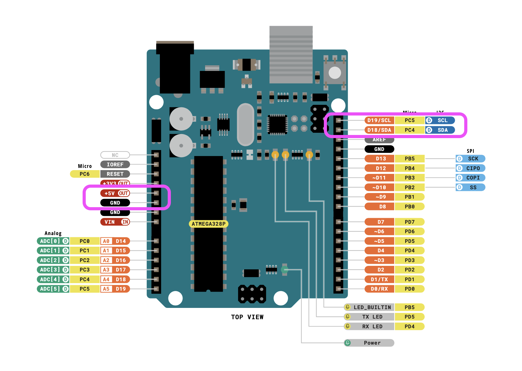
Wire using the STEMMA QT connector.
If you are using a 3V board, like an Adafruit Feather, wire the board's 3V pin to the VL53L4CD VIN.
- Board 5V to sensor VIN (red wire)
- Board GND to sensor GND (black wire)
- Board SCL to sensor SCL (yellow wire)
- Board SDA to sensor SDA (blue wire)
3 Software & code
In the Arduino software Click the Manage Libraries ... menu item (under Tools), search for VL53L4CD, and select the STM32duino VL53L4CD library. Install it.
The library comes with some example sketches, I used one of them and adjusted the code so the useless information like status, signal, tekst is removed. It now only outputs a stream of values.
Open a new arduino file ande replace the code with this:
5 Connect the arduino to your computer.
Connect Arduino to your computer & Upload the code.
If you do not know how to upload a Arduino sketch, please visit https://www.arduino.cc/en/Guide/Windows for Windows user or https://www.arduino.cc/en/Guide/MacOSX for Mac user.
Open the serial monitor by clicking the Magnifying glass in the top right corner of the window.
You might need to change the Baud rate to: 115200 before you get good results. Do this in the top right of the serial monitor field.
You should now see a stream of data measuring the distance to the object in front of the sensor. Hold your hand in front of the sensor and move it.
For connecting with Isadora read this
You can borrow this sensor for testing at the Blackbox location IBB. Contact: blackbox.ibb-pastoe@hku.nl
IR Distance Sensor SHARP GP2Y0A02YK with Arduino
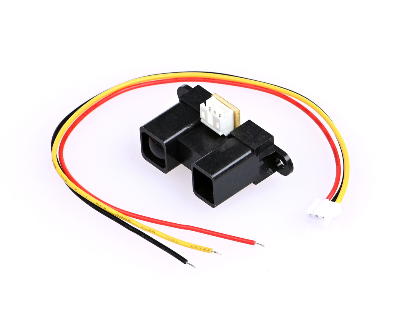
The Sharp GP2Y0A02YK infrared ranger is able to continuously measure the distance to an object. The usable range is 20 cm to 150 cm. The device generates an analog voltage that is a function of range, and the output voltage can be measured by an analog-to-digital (ADC) input line. The voltage will range from approx. 0.4V at 150cm to 2.7V at 20cm.
1 Material:
- sensor: Sharp GP2Y0A02YK
- Arduino UNO (other models also are fine) × 1 + power cable (sold seperately)
- Dupont jumper wires Male - male
- Capacitor(≥10 µF)
- breadboard
Solder some male jumper wires on the cable that comes with the sensor for easy connection to arduino or breadboard.
2 Assembly
Connect the parts according this schematic:
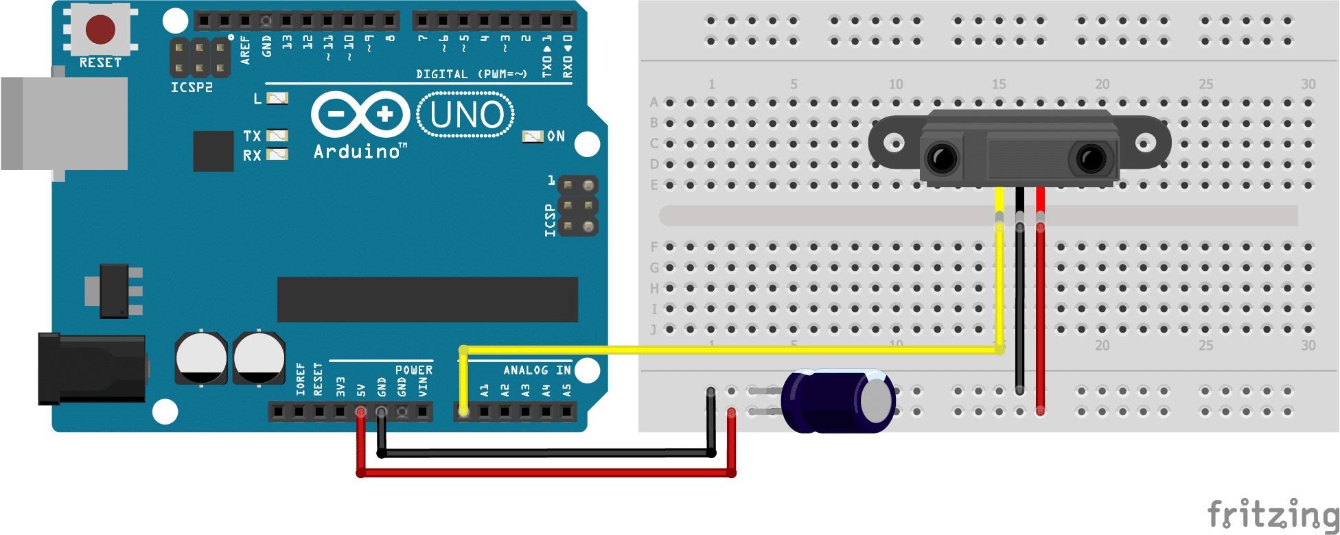
These type of distance sensors tend to be a bit noisy, so it is recommended to add a capacitor between Vcc and GND. The datasheet suggests a capacitor of 10 µF or more (I used 220 µF). Connect the positive lead of the capacitor to the Vcc wire connection and the negative lead to the GND wire connection (see picture). Capacitors are often marked with a stripe which indicates the negative lead. The positive lead is often longer then the negative lead.
3 Software & code
Download the SharpIR library written by Guillaume Rico and Thibaut Mauon here.
For more information check the github page here.
This library is not available through the library manager of Arduino. You have to manually instal it. For how to manually installing a library check this page. Scroll down to: "Importing a .zip Library"
I've edited the code from the source website a little so you only get values and no text as output. Works better with visual programming software like Isadora or touchdesigner.
Copy this code into a new empty file, connect with your arduino and uplaod the code.
4 Connect the arduino to your computer.
Connect Arduino to your computer & Upload the code.
If you do not know how to upload a Arduino sketch, please visit https://www.arduino.cc/en/Guide/Windows for Windows user or https://www.arduino.cc/en/Guide/MacOSX for Mac user.
Open the serial monitor by clicking the Magnifying glass in the top right corner of the window.
You should now see a stream of data measuring the distance to the object in front of the sensor. Hold your hand in front of the sensor and move it.
For connecting with Isadora read this
You can borrow this sensor for testing at the Blackbox location IBB. Contact: blackbox.ibb-pastoe@hku.nl
source:
https://www.makerguides.com/sharp-gp2y0a21yk0f-ir-distance-sensor-arduino-tutorial/